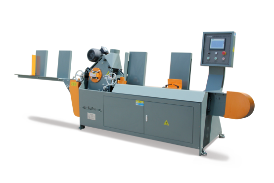
Regolazione e manutenzione dell’attrezzatura
Spegnere l’alimentazione e fermare la macchina prima di effettuare regolazioni o manutenzione. (Nota: la macchina deve essere arrestata)
1.1 Regolazione delle specifiche di lavorazione
L’attrezzatura deve essere regolata quando si passa a specifiche di pannello diverse.
1.1.1 Regolazione delle dimensioni di lavorazione (touchscreen)
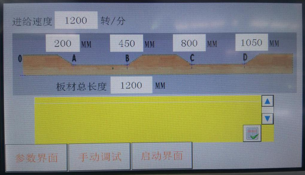
Figura 1-1
Determinare le dimensioni di lavorazione in base ai requisiti; inserire sulla touchscreen la lunghezza totale del pannello e i punti ABCD (punto più basso dell’arco di taglio).
Non modificare arbitrariamente i valori su altre interfacce; tenere traccia delle modifiche per prevenire errori.
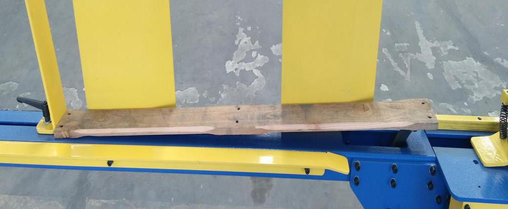
Figura 1-2
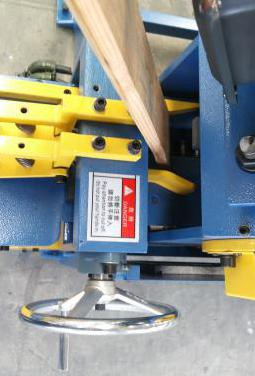
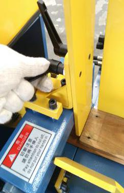
1.1.2 Regolazione della larghezza del caricatore e della pressione laterale sul materiale
1.2.1 Regolazione della tensione della catena principale
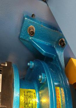
Quando la catena principale si allenta, allentare le viti di fissaggio del motore (Figura 1-9) e lasciare che il motore cada liberamente per tendere la catena. Allineare le scanalature di fissaggio e serrare le viti (Figura 1-10).
1.2.2 Regolazione della tensione della catena trasportatrice
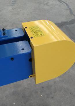
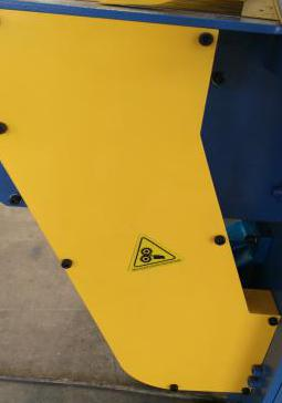
Quando la catena di trasporto diventa allentata, rimuovere il coperchio giallo (Figura 1-8) e regolare le viti di tensionamento su entrambi i lati.
1.2.3 Regolazione della tensione delle cinghie trapezoidali
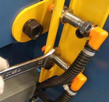
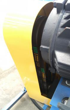
Quando la cinghia trapezoidale è allentata o usurata, rimuovere il coperchio giallo (Figura 1-11) e regolare le viti della piastra del motore per applicare la tensione. Assicurarsi che l’altezza dei dadi sia uniforme.
 |
 |
 |
| Figura 1-12 |
Figura 1-13 |
Figura 1-14 |
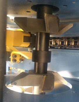
Sostituire tempestivamente le frese usurate o danneggiate. Affilare presso strutture specializzate; eliminare quelle gravemente danneggiate.
Fasi di smontaggio e montaggio della fresa:
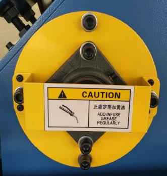
Fase 1: Rimuovere le quattro viti dal disco giallo (Figura 1-12) ed estrarre l’intero disco.
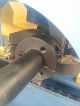
Fase 2: Allentare le viti della ghiera di bloccaggio (Figura 1-13).
Passo 3: Rimuovere il tagliente esterno, la bussola distanziatrice (ciascuna contrassegnata con la misura corrispondente, Figura 1-14) e infine il tagliente interno.
Sostituire la bussola distanziatrice se le dimensioni da lavorare cambiano (ad esempio, per una larghezza di 100 mm si utilizza una bussola da 49 mm; per una larghezza di 110 mm si utilizza una bussola da 59 mm).
Passo 4: Reinstallare il tagliente o la bussola distanziatrice nell’ordine inverso e serrare le viti.
Attenzione: Le frese hanno lame affilate; maneggiarle con cautela. Non utilizzare utensili smussati per colpire; usare un martello in gomma. Utilizzare utensili specifici per viti e dadi; non serrare eccessivamente.

 Notizie in primo piano