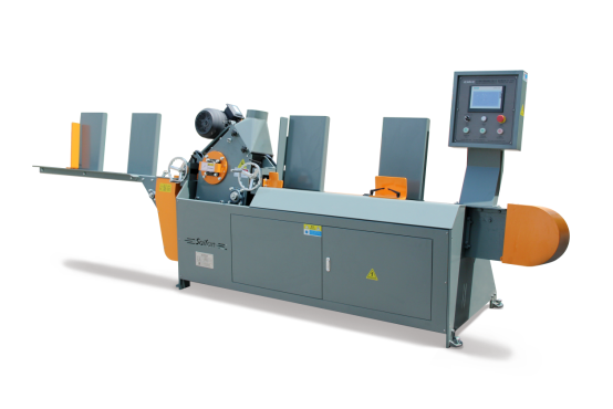
Réglage et entretien de l’équipement
Couper l’alimentation électrique et arrêter la machine avant tout réglage ou entretien. (Remarque : la machine doit être à l’arrêt)
1.1 Réglage des spécifications de traitement
L’équipement doit être réglé lors du passage à des spécifications différentes de panneaux.
1.1.1 Réglage des dimensions de traitement (écran tactile)
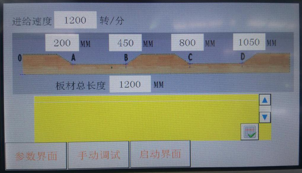
Figure 1-1
Déterminer les dimensions de traitement conformément aux exigences ; saisir sur l’écran tactile la longueur totale du panneau ainsi que les points A, B, C et D (point le plus bas de l’arc de découpe).
Ne pas modifier arbitrairement les valeurs sur d’autres interfaces ; tenir un registre afin d’éviter les erreurs après modification.
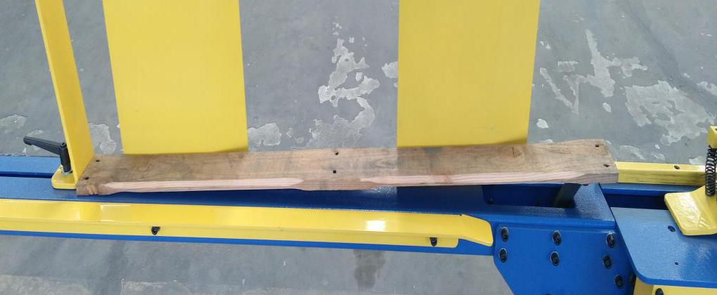
Figure 1-2
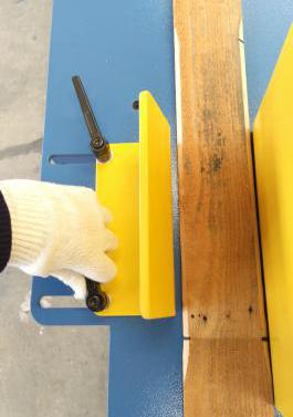
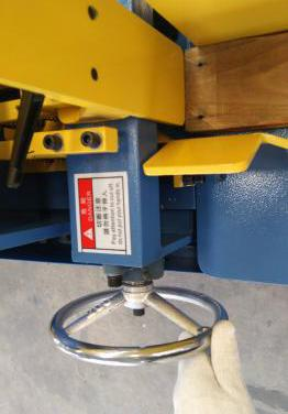
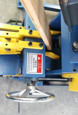
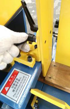
1.1.2 Réglage de la largeur de la trémie et de la pression latérale sur le matériau
1.2.1 Réglage de la tension de la chaîne principale
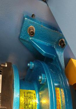
Lorsque la chaîne principale se relâche, desserrer les vis de fixation du moteur (figure 1-9) afin que le moteur puisse descendre librement et tendre la chaîne. Aligner les fentes de fixation, puis resserrer les vis (figure 1-10).
1.2.2 Réglage de la tension de la chaîne transporteuse
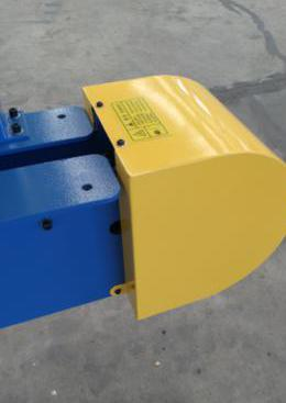
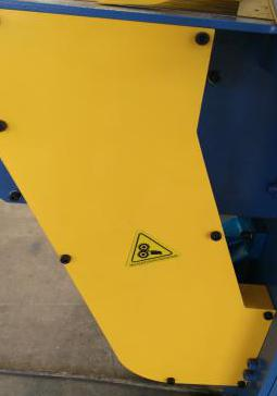
Lorsque la chaîne d’entraînement devient lâche, retirez le couvercle jaune (figure 1-8) et ajustez les vis de tension des deux côtés.
1.2.3 Réglage de la tension des courroies trapézoïdales
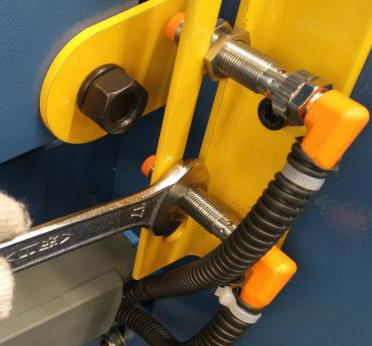
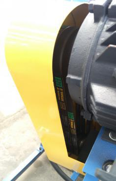
Lorsque la courroie trapézoïdale est lâche ou usée, retirez le couvercle jaune (figure 1-11) et ajustez les vis de la plaque moteur pour tendre la courroie. Assurez-vous que la hauteur des boulons soit uniforme.
 |
 |
 |
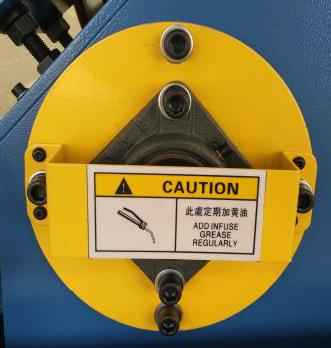
| Figure 1-12 |
Figure 1-13 |
Figure 1-14 |
Remplacez sans délai les fraises usées ou endommagées. Aiguisez-les dans des installations spécialisées ; mettez au rebut celles qui sont gravement endommagées.
Étapes de démontage et de montage de la fraise :
Étape 1 : Retirez les quatre vis du disque jaune (figure 1-12) et retirez l’ensemble du disque.
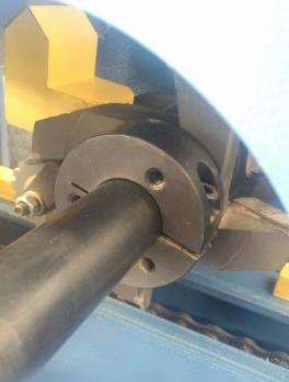
Étape 2 : Desserrez les vis du manchon de blocage (figure 1-13).
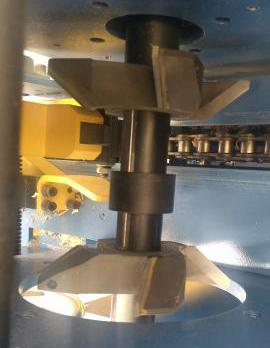
Étape 3 : Retirez le coupeur extérieur, la douille entretoise (chacune portant une marque indiquant sa taille, figure 1-14), puis, enfin, le coupeur intérieur.
Remplacez la douille entretoise si les dimensions à usiner changent (par exemple, une largeur de 100 mm nécessite une douille de 49 mm ; une largeur de 110 mm nécessite une douille de 59 mm).
Étape 4 : Réinstallez le coupeur ou la douille entretoise dans l’ordre inverse, puis serrez les vis.
Attention : Les fraises comportent des lames tranchantes ; manipulez-les avec précaution. N’utilisez pas d’outils émoussés pour frapper ; utilisez un maillet en caoutchouc. Employez des outils dédiés pour les vis et les écrous ; ne les surserrez pas.

 Actualités chaudes