
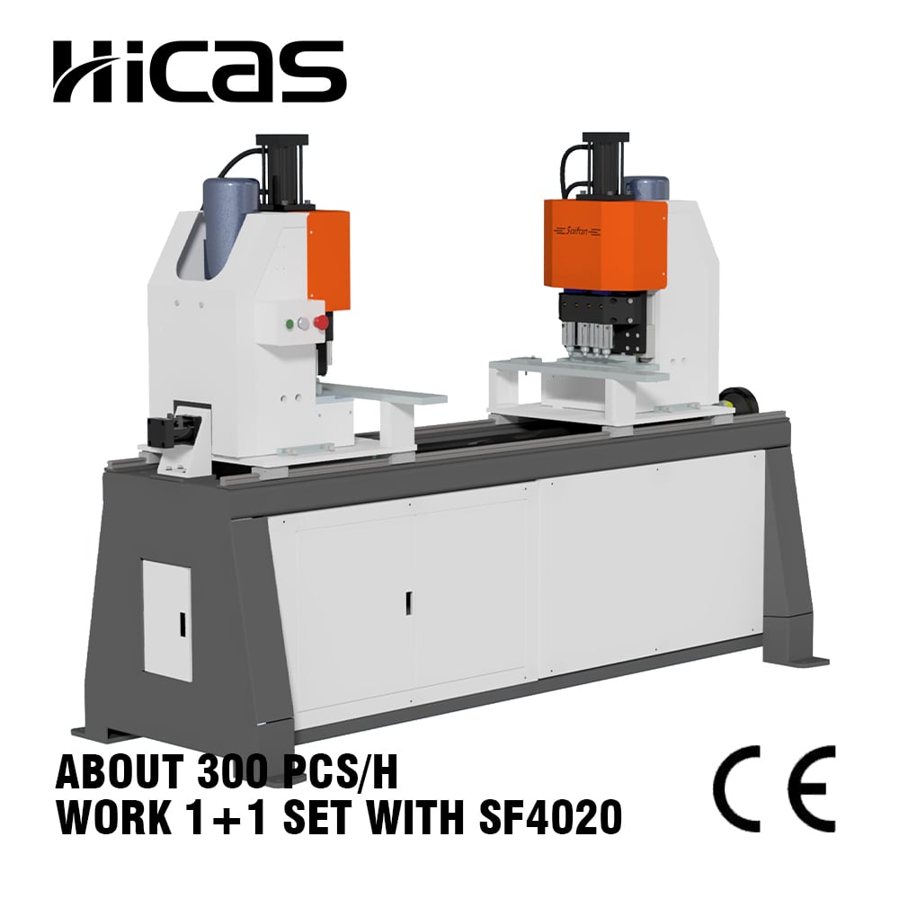
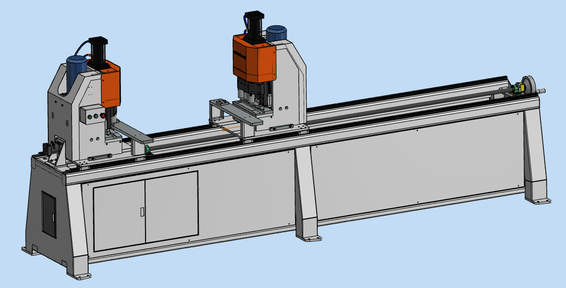
1. Installation of the Machine Tool’s Mechanical Components
 |
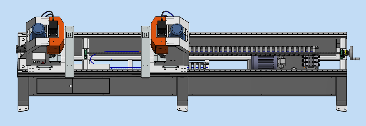 |
| Figure 1 | Figure 2 |
2. Electrical Wiring and Grounding of the Machine Tool
Ensure that the main power supply in the workshop meets the electrical requirements of the machine tool. Check that the main voltage matches the machine’s operating voltage.
Determine the cable cross-sectional area according to the total power capacity of the machine. For this model, users are recommended to use copper cables with a cross-sectional area of at least 4 mm². The protection current of the overcurrent protection device should be set to approximately 40 A.
Ensure that the machine tool is reliably grounded. Refer to Figure 4 for the machine safety grounding diagram.
Determine the cable entry point according to the production layout, and connect the cable to the machine tool terminals as shown in Figure 4. Check the direction of motor rotation.
 |
 |
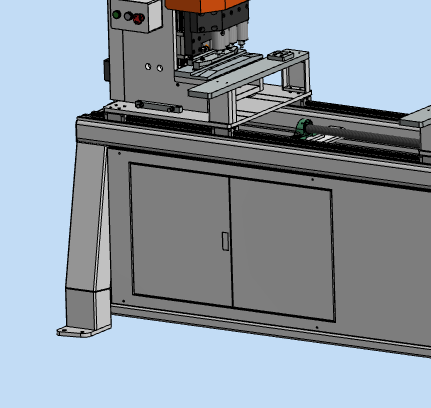
| Figure 3 | Figure 4 |
Note: When wiring the machine, the user must follow the accompanying electrical schematic. The machine’s electrical system must be wired and maintained by a properly trained electrician.
3. Installation of the Dust Extraction System
The dust extraction system required for this machine must provide an airflow of 9,500 m³/h, a static pressure of 2,300 Pa, and an air velocity of 25–30 m/s.
The user is responsible for connecting all dust extraction ports on the machine to the dust collection unit. The dimensions of the dust extraction ports are shown in Figure 3-6. Ensure that the dust extraction ducts are tightly and securely connected to all dust extraction ports on the machine.
The resistance of the externally connected dust extraction duct must be less than 10 Ω. After connecting the duct to the dust extraction port, ensure that the vacuum at the connection is maintained at 110–130 mm water column.
Note: Keep the dust collection unit away from heat-dissipation equipment, damp areas, and high-voltage locations.
Warning: The dust collection unit must be started before starting the cutoff saw.
4. Connecting the Compressed Air Supply to the Machine Tool
Ensure that the workshop air supply meets the requirements of the machine tool. Only an adequate air supply can ensure optimal machine performance.
The compressed air supplied by the air source must be dry and free of water, and must meet the following requirements:
- Internal diameter of the air supply pipe: ≥ Ø6.5 mm
- Air pressure: 0.5–0.8 MPa
- Air consumption: 0.1 m³/min
Refer to the pneumatic schematic of the machine tool and familiarize yourself with the operating principles and procedures of the following pneumatic components in the air preparation unit supplied with the machine. The air preparation unit is installed at the lower end of the machine’s infeed side.
4.1 Air Filter and Lubricator (See Figure 5)
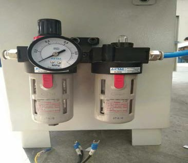
Figure 5
The unit uses cyclone blades to separate moisture and a sintered steel-ball microporous element to trap dust, providing dry and clean air throughout the pneumatic circuit. The separated moisture and dust can be clearly observed through the transparent bowl. The user should determine the correct drainage interval according to the amount collected and open the valve beneath the bowl to discharge it.
The unit uses compressed air as the power source to atomize the lubricating oil and lubricate the pneumatic components. The oil flow can be adjusted by using the adjustment control to regulate the dripping rate.
4.2 Pressure Regulator and Pressure Gauge (See Figure 6)
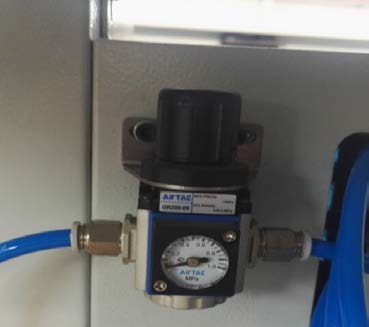
Figure 6
The pressure regulator and pressure gauge are connected together and linked to the air filter and lubricator. To adjust the pressure regulator, first pull out the adjustment knob and rotate it until the output working pressure is approximately 0.4 MPa. After adjustment, press the knob down to lock it back into position.
5. Machine Tool Emergency Stop

Figure 7
In an emergency, press the “EM.STOP” button on the machine’s electrical control panel or pull the emergency stop cable.
The machine will stop immediately, and the “EM.STOP” fault indicator light will turn on.
Note: Use the “EM.STOP” button only in an emergency. Frequent use may cause premature damage to the button.
6. Motor Protection
The control circuit is equipped with automatic motor overload protection.
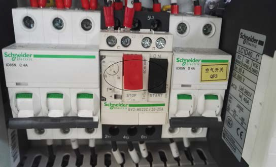
Figure 8