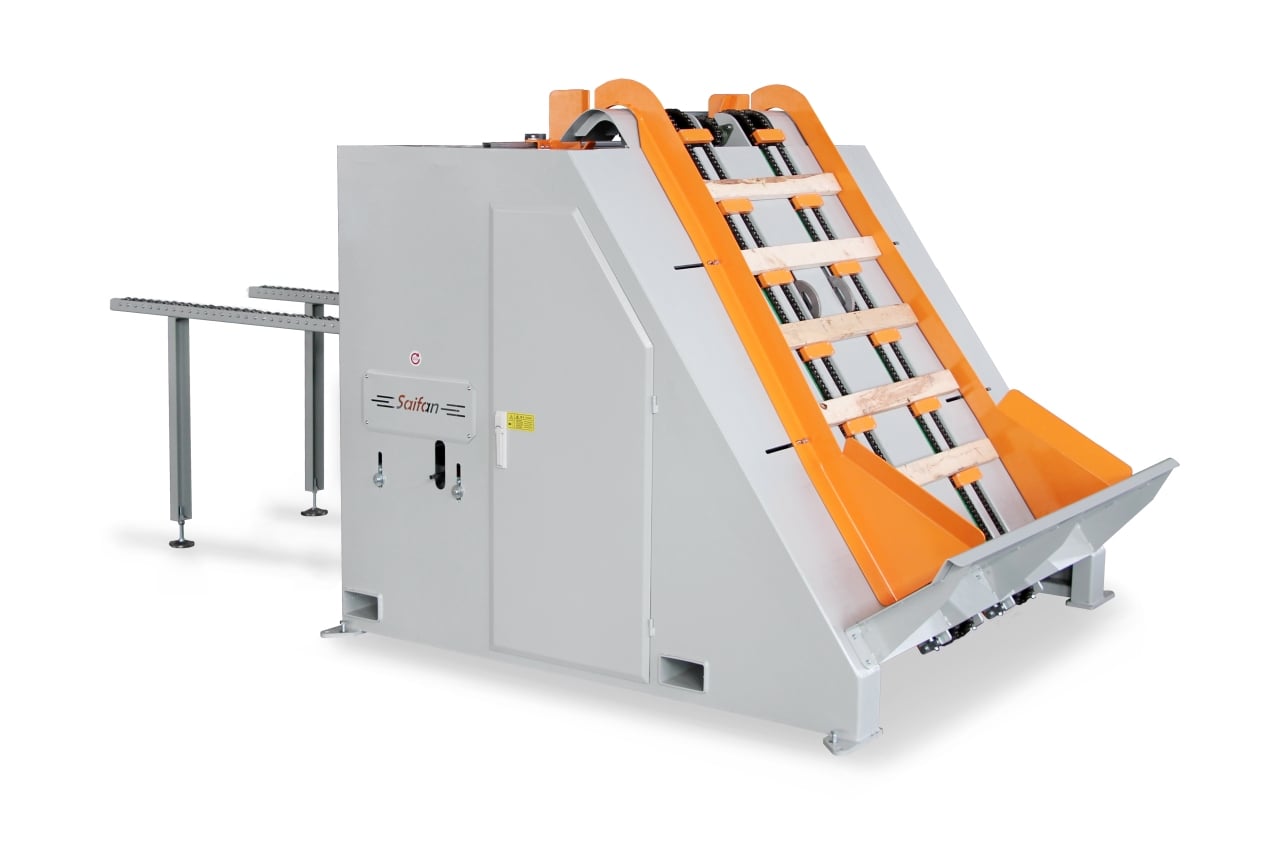
1. Adjustment of Processing Specifications
To prevent damage to accessories or malfunctions during the adjustment process, be sure to follow this adjustment sequence.
Sequence when increasing specifications:
Alignment plate width → Baffle plate width → Notching spacing → Notching depth
Sequence when decreasing specifications:
Notching spacing → Alignment plate width → Baffle plate width → Notching depth
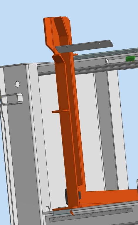
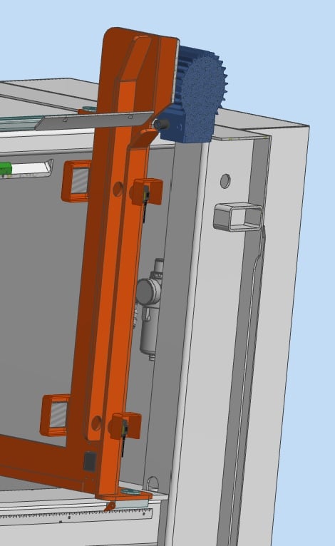
2. Adjusting the Length and Thickness of the Board (Alignment Plate)
Adjust the width of the alignment plate according to the length of the board in millimeters (Figure 6-1, Figure 6-2):
- Taking a board length of B=1000mm as an example, roughly adjust the left and right sets of alignment plates to B/2=500mm.
- Place a wooden board at the feeding end, fine-tune the alignment plate to allow a 1-2mm wiggle gap, and tighten the handle.
- Place a board at the discharge end, fine-tune the alignment plate to allow a 1-2mm wiggle gap, and tighten the handle.
- Taking a board thickness of C=38mm as an example, loosen and adjust the front stopper so the width is about 5mm larger than the board thickness, then lock the handle.
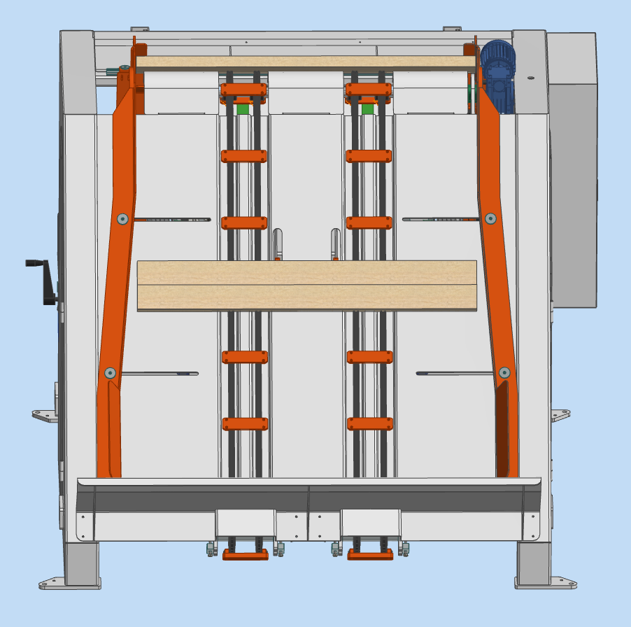
3. Adjusting the Baffle Plate Width
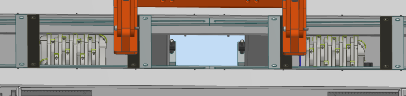
Adjust the baffle plate width according to the board length in millimeters (Figure 6-3). Align the baffle plate with the alignment plate, making it slightly larger. Place a board into the baffle plate, fine-tune for a 5mm wiggle gap, and tighten the screws.
4. Adjusting the Notching Spacing
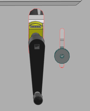
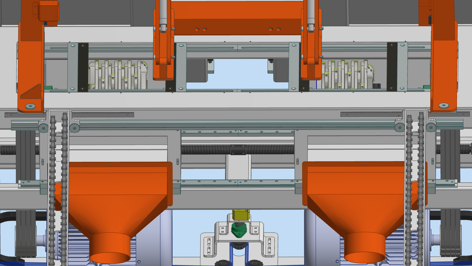
Adjust the notching spacing (outer spacing of the notches) according to the board requirements. The value on the position display multiplied by 2 is the notching spacing in millimeters (Figure 6-4).
Before adjusting the spacing, loosen the screws of the support backing plate (Figure 6-5) and move it away from the cutter body. Loosen the lock screw, use the crank handle to adjust while watching the position display, and release the button when the required size is reached. Move the support plate close to the cutter, rotate the cutter body to ensure a ~0.5mm gap between the cutter and the plate, then tighten the screws.
5. Adjusting the Notching Depth
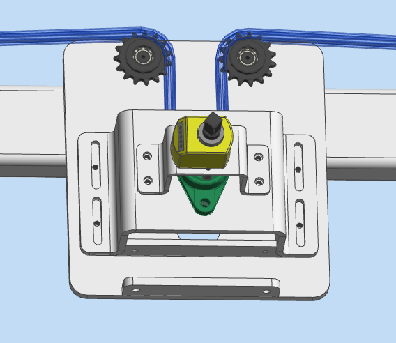
Adjust the notching depth according to the board requirements. The reading on the position display is the notching depth in millimeters (Figure 6-6).
First, loosen the lock screws of the guide rail frame (Figure 6-4).
- ① Loosen the lock screw at this position.
- ② Use the crank handle to adjust the height of the work platform; the reading on the display is the notching depth.
- ③ Tighten the lock screw after adjustment (Figure 6-6).
Note: Do not adjust the reading to less than 0000.0mm or more than 0070.0mm.
6. Tension Adjustment of the Transmission V-Belt
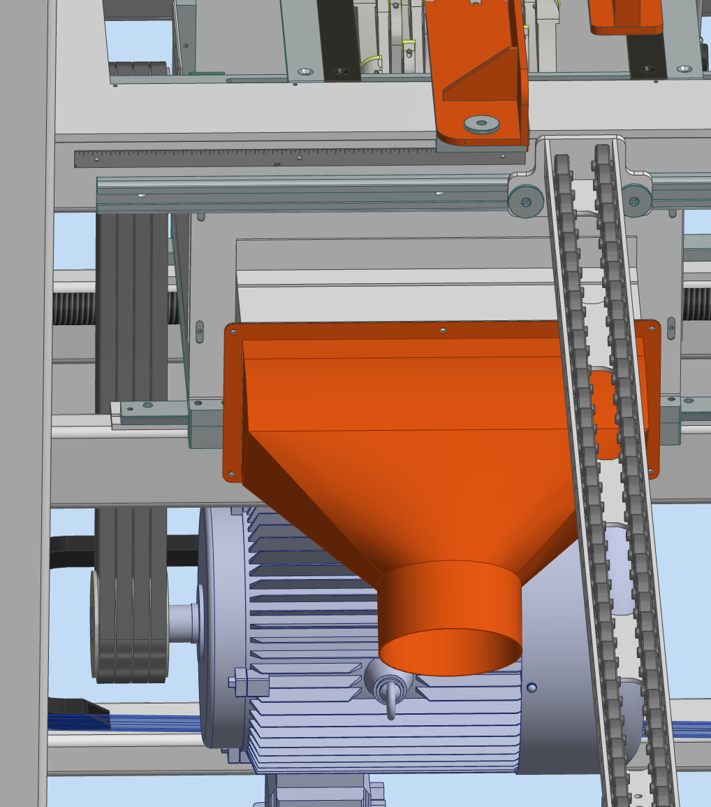
After the equipment has been used for a period, the V-belt will become loose. It needs to be tensioned to ensure sufficient driving force.
Open the front sheet metal door, loosen the nut on the motor fixing screw rod, adjust the motor downward until the V-belt is tensioned, then lock the nut (Figure 6-7). When the V-belt is severely worn or broken, it must be replaced with a new one (V-belt Type B Li1499).
7. Tension Adjustment of the Lifting Conveyor Chain
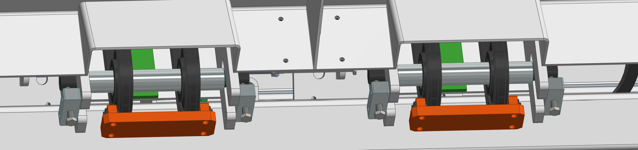
When the chain becomes loose after use, it needs tensioning. Adjust the tension screws on both sides (Figure 6-8) simultaneously to tension the chain, then lock the nuts.
8. Replacement of Milling Cutter Body or Blades
Adding or Reducing Milling Cutter Bodies
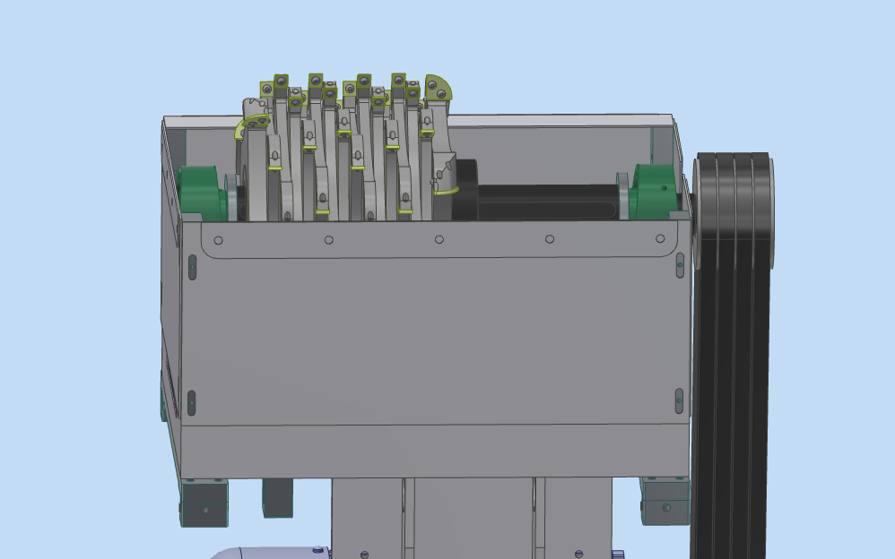
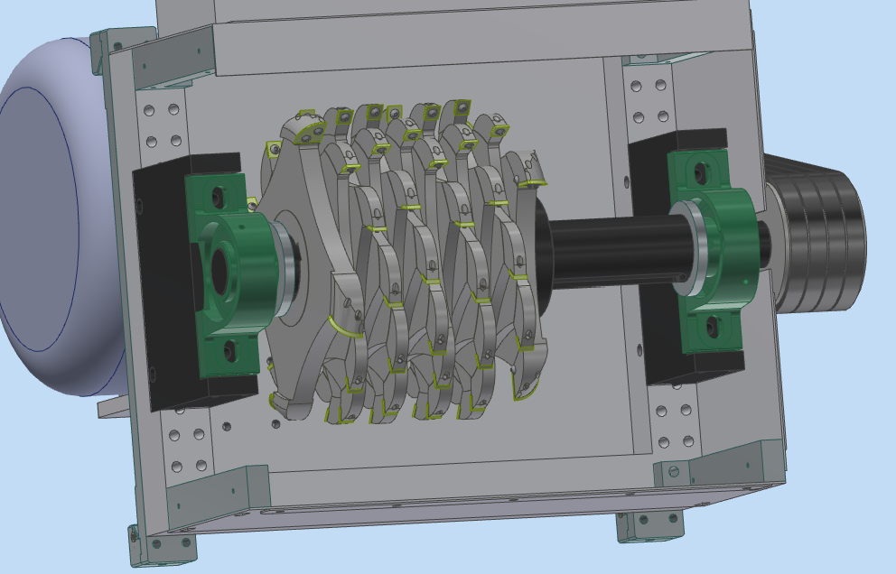
Due to different notch width requirements, the number of cutter bodies needs to be adjusted. The standard factory configuration is one set of 2 side cutters (1 left, 1 right) and 14 middle cutters, with a total width of 228.6mm (9in). The maximum total width is 368.3mm (29/2in).
Disassembly/Assembly Steps:
- Step 1: Adjust the alignment plate to the maximum size, remove the dust suction port, and open the rear shield door.
- Step 2: Loosen the screws of the support backing plates on both sides and move them away from the cutter body (Figure 6-9).
- Step 3: Loosen the screws on the dustproof plate and remove it (Figure 6-10).
- Step 4: Loosen the tightening screw on the bearing, use the special wrench to loosen the screws fixing the milling cutter seat, and remove the bearing and seat together (Figure 6-11).
- Step 5: Remove the spacer sleeve and remove or add cutter bodies one by one (Figure 6-11).
- Step 6: Reinstall in reverse order, ensuring all screws are secure.
Caution: Handle with care when blades are installed to avoid injury. Do not use blunt instruments for forceful striking; use a rubber mallet instead. Use professional tools and appropriate force to avoid damaging parts or causing injury.
Replacement of Milling Cutter Blades
Recommended to check blade wear before work daily. Replace damaged blades promptly for safety and efficiency. No need to remove the cutter body when replacing blades.
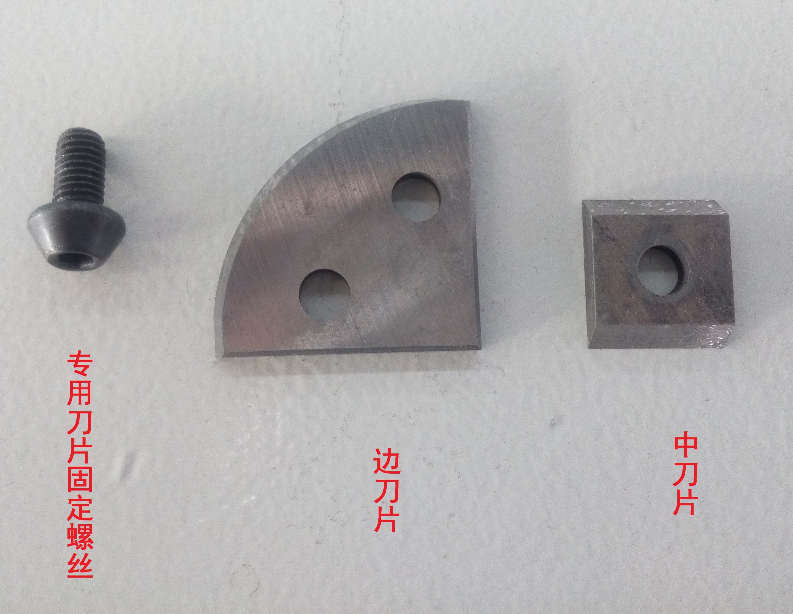
Key points for disassembly/assembly:
- Use special tools to remove blades.
- Replace blades when they are dull or jagged. If the middle blade is intact, it can be rotated 180° to use the other cutting edge.
- Clean the installation position on the cutter body.
- The middle blade must be centered and close to the cutter body; side blades must be snapped into the steps.
- Secure blades with special fixing screws (Figure 6-12).


 Hot News